

4G Smart Motor Control Box (No Contactor)
Applications
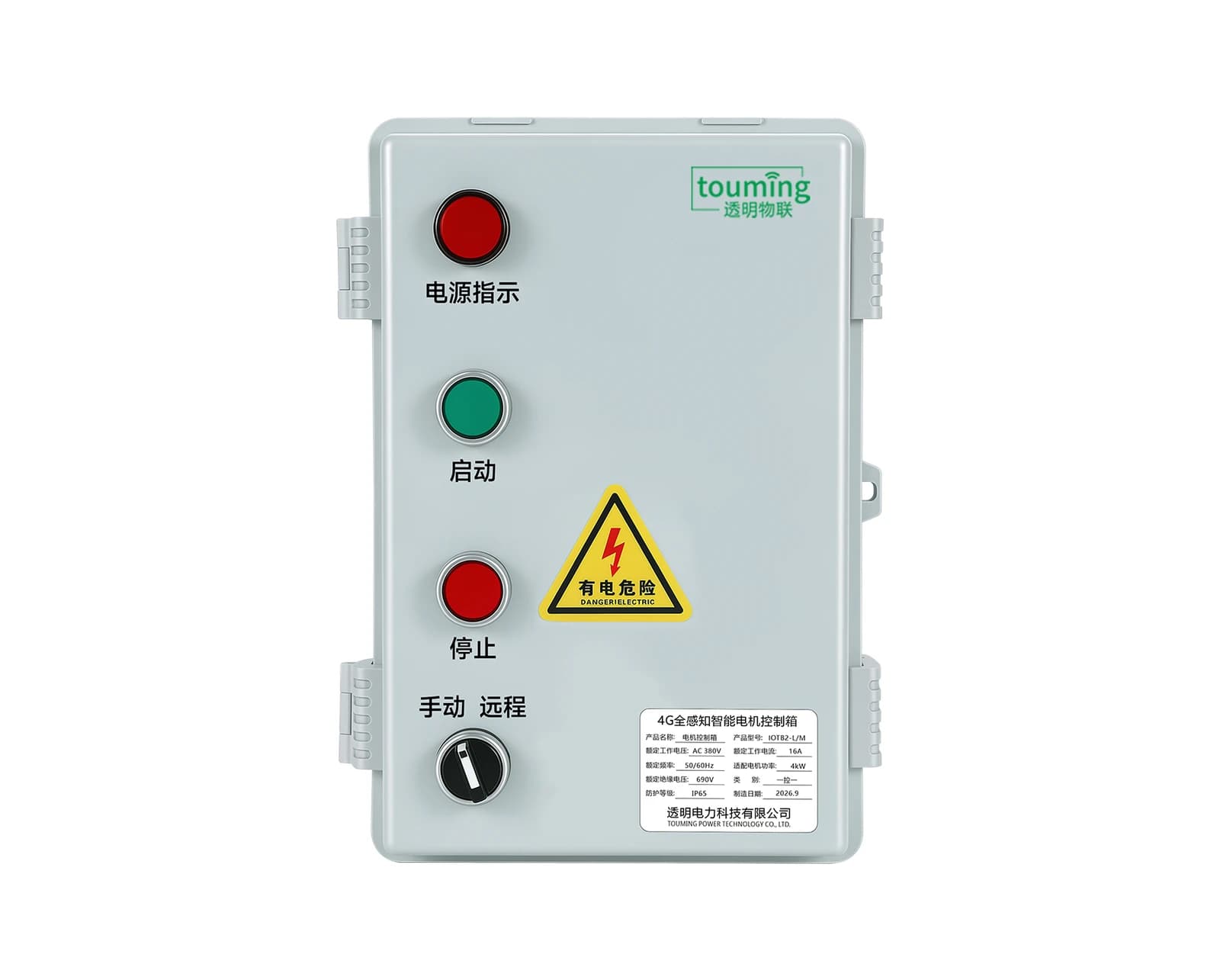
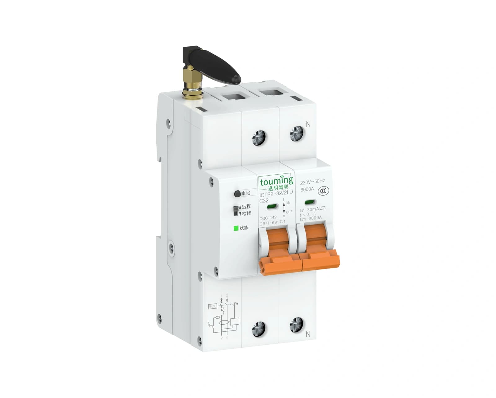
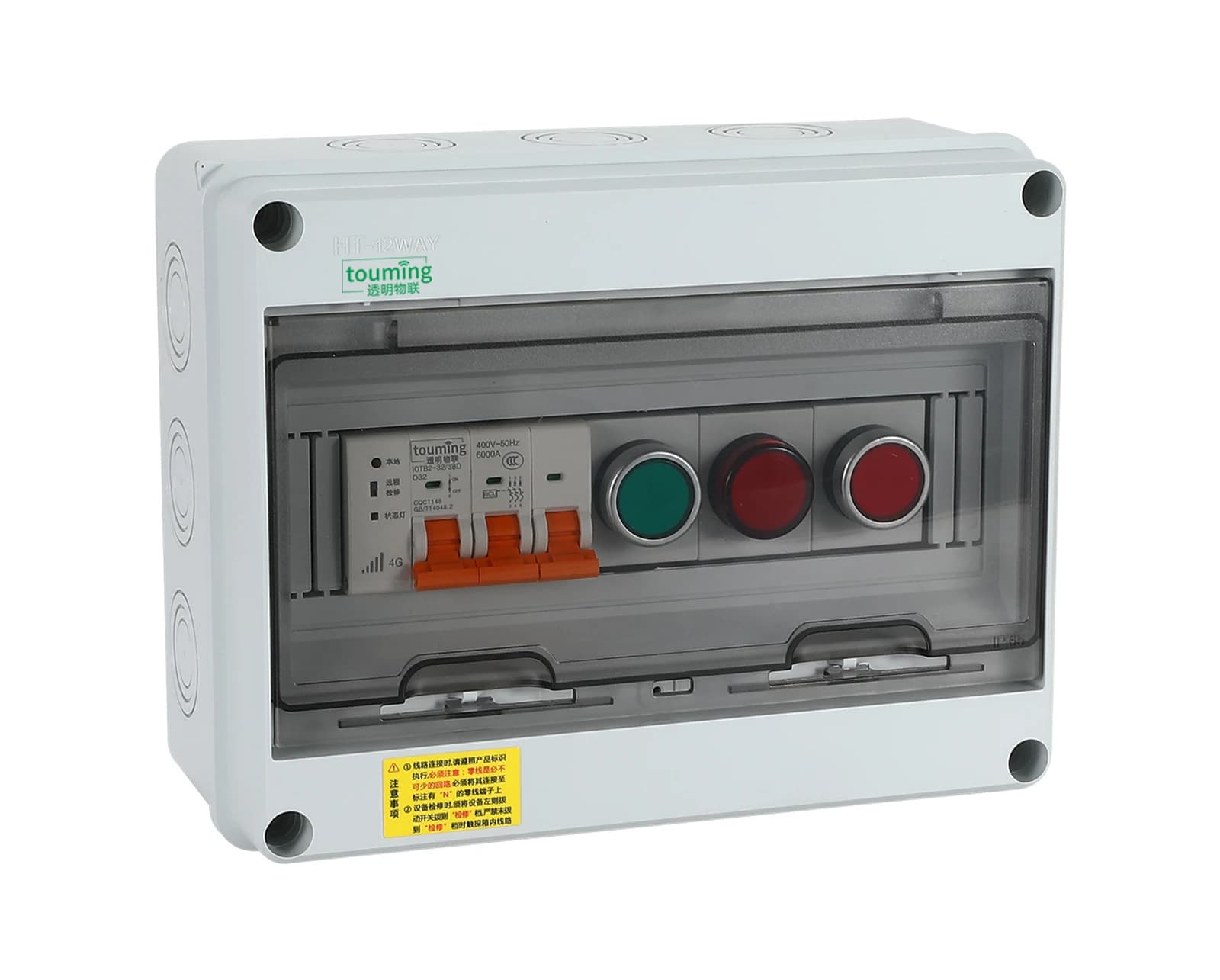
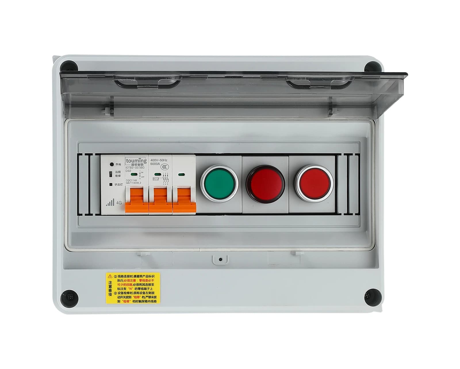
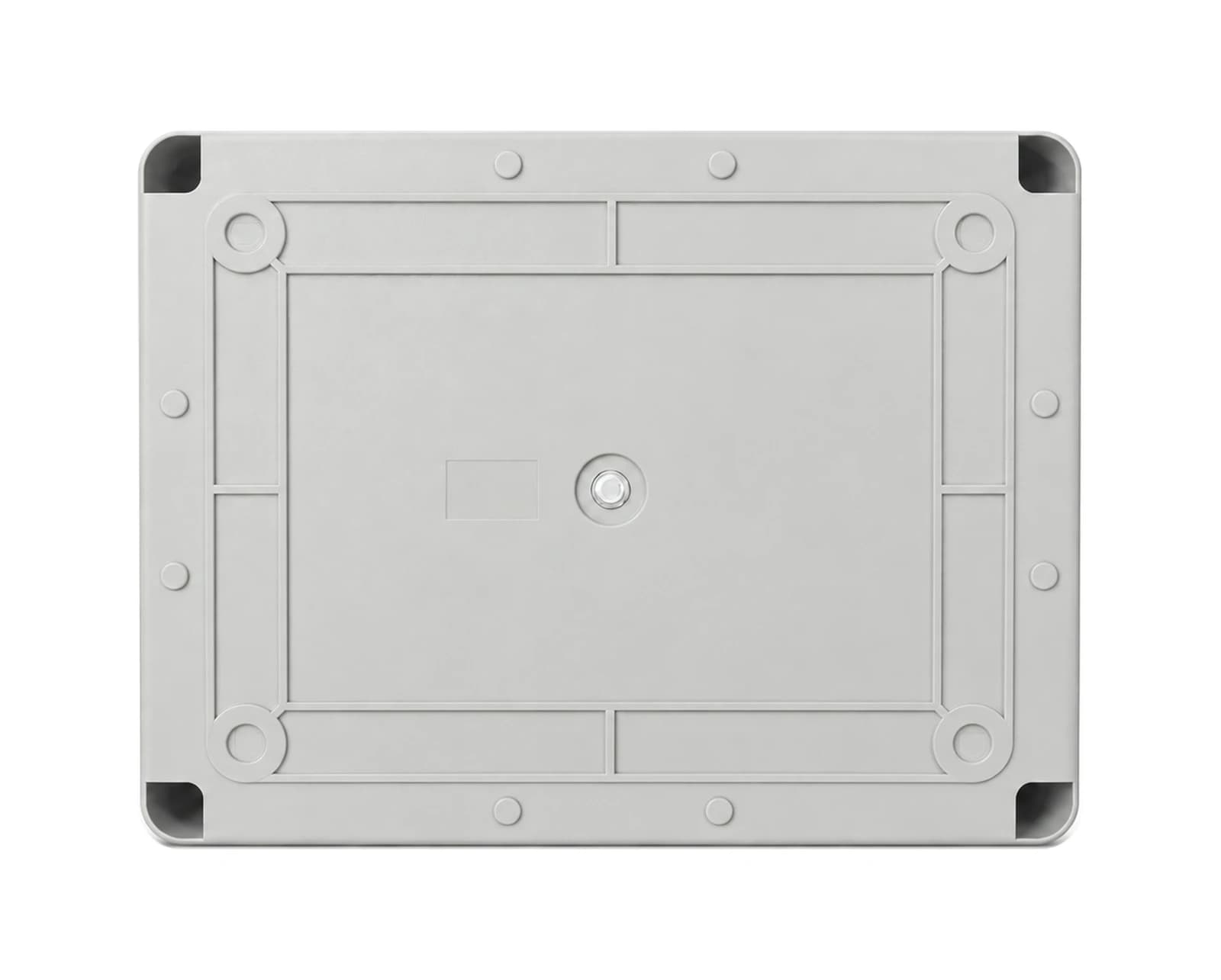
Version A switches the motor’s main circuit directly with the IOTB2 4G smart breaker and has no AC contactor. Its compact enclosure (198 × 255 × 110 mm) suits pumps, fans, aerators and conveyors that start infrequently; operators start and stop it on site or from a phone or computer and see electrical data and alarms in real time.
Appearance and Mounting
Power Selection Reference
- Motor power kW
- 0.75
- Motor current A
- 1.9
- Breaker A
- 6
- Overcurrent setting A
- 2.1
- Copper cross-section mm²
- 1.5
- Motor power kW
- 1.1
- Motor current A
- 2.7
- Breaker A
- 6
- Overcurrent setting A
- 3.0
- Copper cross-section mm²
- 1.5
- Motor power kW
- 1.5
- Motor current A
- 3.7
- Breaker A
- 6
- Overcurrent setting A
- 4.1
- Copper cross-section mm²
- 1.5
- Motor power kW
- 2.2
- Motor current A
- 5.0
- Breaker A
- 10
- Overcurrent setting A
- 5.5
- Copper cross-section mm²
- 1.5
- Motor power kW
- 3.0
- Motor current A
- 6.8
- Breaker A
- 10
- Overcurrent setting A
- 7.5
- Copper cross-section mm²
- 1.5
- Motor power kW
- 4.0
- Motor current A
- 8.8
- Breaker A
- 16
- Overcurrent setting A
- 9.7
- Copper cross-section mm²
- 2.5
- Motor power kW
- 5.5
- Motor current A
- 11.6
- Breaker A
- 16
- Overcurrent setting A
- 12.8
- Copper cross-section mm²
- 2.5
- Motor power kW
- 7.5
- Motor current A
- 15.4
- Breaker A
- 25
- Overcurrent setting A
- 16.9
- Copper cross-section mm²
- 4
- Motor power kW
- 11
- Motor current A
- 22.6
- Breaker A
- 32
- Overcurrent setting A
- 24.9
- Copper cross-section mm²
- 6
- Motor power kW
- 15
- Motor current A
- 30.0
- Breaker A
- 40
- Overcurrent setting A
- 33.0
- Copper cross-section mm²
- 6
- Motor power kW
- 18.5
- Motor current A
- 36.0
- Breaker A
- 50
- Overcurrent setting A
- 39.6
- Copper cross-section mm²
- 10
- Motor power kW
- 22
- Motor current A
- 43.0
- Breaker A
- 63
- Overcurrent setting A
- 47.3
- Copper cross-section mm²
- 10
| Motor power kW | Motor current A | Breaker A | Overcurrent setting A | Copper cross-section mm² |
|---|---|---|---|---|
| 0.75 | 1.9 | 6 | 2.1 | 1.5 |
| 1.1 | 2.7 | 6 | 3.0 | 1.5 |
| 1.5 | 3.7 | 6 | 4.1 | 1.5 |
| 2.2 | 5.0 | 10 | 5.5 | 1.5 |
| 3.0 | 6.8 | 10 | 7.5 | 1.5 |
| 4.0 | 8.8 | 16 | 9.7 | 2.5 |
| 5.5 | 11.6 | 16 | 12.8 | 2.5 |
| 7.5 | 15.4 | 25 | 16.9 | 4 |
| 11 | 22.6 | 32 | 24.9 | 6 |
| 15 | 30.0 | 40 | 33.0 | 6 |
| 18.5 | 36.0 | 50 | 39.6 | 10 |
| 22 | 43.0 | 63 | 47.3 | 10 |
Motor current and overcurrent settings are reference values; the motor nameplate governs. Copper cross-sections are a guide only; have long, hot or bundled runs checked by a qualified professional.
Protection Functions
- Protection
- Start timeout
- Default trigger
- Start current ≥ frame current × 3.0 not falling back within 10.0 s
- Response method
- Motorized trip and event log
- Protection
- Overload
- Default trigger
- Any phase ≥ frame current × 1.45 for 3.0 s
- Response method
- Motorized trip and event log
- Protection
- Underload
- Default trigger
- All phases < frame current × 0.3 for 10.0 s (off by default)
- Response method
- Event log; optional trip and delayed auto-reclose
- Protection
- Locked rotor
- Default trigger
- After start-up, any phase ≥ frame current × 4.0 for 1.0 s
- Response method
- Motorized trip and event log
- Protection
- Phase loss
- Default trigger
- Any phase voltage < 50.0 V for 3.0 s
- Response method
- Alarm; optional trip
- Protection
- Short circuit
- Default trigger
- Breaker instantaneous trip level (about frame current × 10)
- Response method
- Instantaneous breaker trip
- Protection
- Earth leakage (L models)
- Default trigger
- Residual current ≥ 30 mA for 0.1 s
- Response method
- Motorized trip; 1–3 auto-recloses can be set
- Protection
- Power overload
- Default trigger
- Total active power ≥ rated power × 1.2 for 60 s
- Response method
- Alarm only by default; optional trip
- Protection
- Overvoltage
- Default trigger
- Any phase ≥ 275.0 V for 1.0 s
- Response method
- Motorized trip; optional delayed reclose once the voltage recovers
- Protection
- Undervoltage
- Default trigger
- Any phase ≤ 176.0 V (not a power loss) for 3.0 s
- Response method
- Motorized trip; optional delayed reclose once the voltage recovers
- Protection
- Phase imbalance
- Default trigger
- Current imbalance ≥ 30% with the highest phase ≥ frame current × 0.2, for 5.0 s
- Response method
- Alarm; optional trip
- Protection
- Power loss
- Default trigger
- All phases < 50.0 V or mains lost for 3.0 s
- Response method
- Built-in backup power reports the outage
- Protection
- External fault
- Default trigger
- Dry-contact input (temperature, flooding, door) active for 1.0 s
- Response method
- Alarm; optional trip
| Protection | Default trigger | Response method |
|---|---|---|
| Start timeout | Start current ≥ frame current × 3.0 not falling back within 10.0 s | Motorized trip and event log |
| Overload | Any phase ≥ frame current × 1.45 for 3.0 s | Motorized trip and event log |
| Underload | All phases < frame current × 0.3 for 10.0 s (off by default) | Event log; optional trip and delayed auto-reclose |
| Locked rotor | After start-up, any phase ≥ frame current × 4.0 for 1.0 s | Motorized trip and event log |
| Phase loss | Any phase voltage < 50.0 V for 3.0 s | Alarm; optional trip |
| Short circuit | Breaker instantaneous trip level (about frame current × 10) | Instantaneous breaker trip |
| Earth leakage (L models) | Residual current ≥ 30 mA for 0.1 s | Motorized trip; 1–3 auto-recloses can be set |
| Power overload | Total active power ≥ rated power × 1.2 for 60 s | Alarm only by default; optional trip |
| Overvoltage | Any phase ≥ 275.0 V for 1.0 s | Motorized trip; optional delayed reclose once the voltage recovers |
| Undervoltage | Any phase ≤ 176.0 V (not a power loss) for 3.0 s | Motorized trip; optional delayed reclose once the voltage recovers |
| Phase imbalance | Current imbalance ≥ 30% with the highest phase ≥ frame current × 0.2, for 5.0 s | Alarm; optional trip |
| Power loss | All phases < 50.0 V or mains lost for 3.0 s | Built-in backup power reports the outage |
| External fault | Dry-contact input (temperature, flooding, door) active for 1.0 s | Alarm; optional trip |
These are factory defaults. Phase-loss and power-loss thresholds and delays are fixed and the short-circuit trip level is set by the fitted breaker; the other settings can be adjusted on the platform within their ranges to match the motor nameplate. Models with “L” in the code include residual-current protection (30 mA by default).
Communication and Platform
- Item
- Cellular network
- Specification
- 4G Cat.1 on China Mobile, China Unicom and China Telecom
- Item
- Data reporting
- Specification
- Every 5 minutes in normal operation; status changes reported at once
- Item
- Platform and protocol
- Specification
- Mini program / app / web; MQTT to the cloud
- Item
- Local interface
- Specification
- RS-485 Modbus RTU, brought out to order
- Item
- Platform features
- Specification
- Live electrical data, grouping, remote and batch start/stop, history curves with Excel export, weekly schedules, in-app and SMS alarms
- Item
- Integration and OEM
- Specification
- API licensed per project; custom branding, labels, packaging and component layout
| Item | Specification |
|---|---|
| Cellular network | 4G Cat.1 on China Mobile, China Unicom and China Telecom |
| Data reporting | Every 5 minutes in normal operation; status changes reported at once |
| Platform and protocol | Mini program / app / web; MQTT to the cloud |
| Local interface | RS-485 Modbus RTU, brought out to order |
| Platform features | Live electrical data, grouping, remote and batch start/stop, history curves with Excel export, weekly schedules, in-app and SMS alarms |
| Integration and OEM | API licensed per project; custom branding, labels, packaging and component layout |
Main technical parameters
- Item
- Rated current
- Specification
- 6–80 A, set by motor power
- Item
- Dimensions
- Specification
- 198 × 255 × 110 mm
- Item
- Mounting holes
- Specification
- 192 × 138 mm
- Item
- Rated frequency
- Specification
- 50 Hz (confirm the configuration for 60 Hz supplies)
- Item
- Internal breaker
- Specification
- IOTB2; 3P / 4P; AC 400 V, 50 Hz; Icn 6000 A
- Item
- Metering
- Specification
- Voltage, current, active power, power factor and energy, class 1.0
- Item
- Standby power consumption
- Specification
- 1–2 W
- Item
- Operating temperature
- Specification
- -20 ℃~+60 ℃
- Item
- Storage temperature
- Specification
- -40 ℃~+70 ℃, non-condensing
- Item
- Relative humidity
- Specification
- ≤ 95%, non-condensing
- Item
- Altitude
- Specification
- ≤ 2000 m
- Item
- Installation method
- Specification
- Wall-mounted with back-plate bolts; suitable outdoors but not submersible
| Item | Specification |
|---|---|
| Rated current | 6–80 A, set by motor power |
| Dimensions | 198 × 255 × 110 mm |
| Mounting holes | 192 × 138 mm |
| Rated frequency | 50 Hz (confirm the configuration for 60 Hz supplies) |
| Internal breaker | IOTB2; 3P / 4P; AC 400 V, 50 Hz; Icn 6000 A |
| Metering | Voltage, current, active power, power factor and energy, class 1.0 |
| Standby power consumption | 1–2 W |
| Operating temperature | -20 ℃~+60 ℃ |
| Storage temperature | -40 ℃~+70 ℃, non-condensing |
| Relative humidity | ≤ 95%, non-condensing |
| Altitude | ≤ 2000 m |
| Installation method | Wall-mounted with back-plate bolts; suitable outdoors but not submersible |
Installation and Use Notes
- A qualified electrician must install and wire the box with the power off. Keep cable entries facing down, tighten and seal the glands and plug unused holes to keep IP65.
- Avoid spots that block 4G, such as inside metal cabinets; fit the optional external antenna where the signal is weak.
- If 4G or the platform drops out, the box keeps its current state and remote control is unavailable; go by the on-site status.
- Stop the motor and open the upstream isolator before maintenance; the motor may restart when power returns, so guard against unexpected starts.
- Supplied with the control box, manual, certificate/warranty card, waterproof glands and mounting parts; 12-month warranty.
- When ordering, give the full model, quantity, motor power and nameplate current, supply voltage and frequency, and say whether you need residual-current protection, an external antenna, RS-485 or OEM customization.